Chapter 10: Boolean Logic, Two's Complement & the 36-Bit Word
In the summer of 1937, twenty-one-year-old MIT master's student Claude Elwood Shannon stood in the basement of MIT's electrical engineering department tending Vannevar Bush's Differential Analyzer alongside hundreds of brass gears and electromechanical telephone relays (Shannon, 1938). That hundred-ton mechanical analog computer used spinning steel shafts, wheel-and-disc integrators, and mechanical torque amplifiers to integrate differential equations through physical rotation. Beneath the display glass of a digital calculator, however, a silicon processor contains no continuous slide-rule scales or spinning shafts—only microscopic switches that are either ON or OFF.
Every time a physicist or ballistician brought a new system of differential equations to the MIT laboratory, Shannon had to configure two distinct subsystems: the continuous mechanical shafts of the differential analyzer, and a complex switching panel of over one hundred electromechanical telephone relays that controlled its clutches, limit switches, and safety interlocks. How could an array of two-state switches represent signed integers, floating-point mantissas, and error-corrected messages?
10.1 Positional Radices, Boolean Switching Algebra & the 36-Bit Word
While wiring those telephone relays in series and in parallel, Shannon recognized the exact algebraic structure of two-valued Boolean logic over \(\{0, 1\}\). If a proposition or signal line is true (asserted), it carries the value \(1\); if it is false (unasserted), it carries the value \(0\). Combining two statements with logical conjunction (AND) behaves like algebraic multiplication (\(1 \cdot 1 = 1\), while \(1 \cdot 0 = 0 \cdot 1 = 0 \cdot 0 = 0\)); combining them with inclusive disjunction (OR) behaves like saturating addition (\(1 + 0 = 1\) and \(1 + 1 = 1\), governed by the idempotent laws \(A + A = A\) and \(A \cdot A = A\)); and negating a statement with NOT inverts \(1 \leftrightarrow 0\) (\(\overline{1} = 0,\; \overline{0} = 1\)), linked by De Morgan's duality identities:
Before the racks of clicking telephone relays in the MIT basement, Shannon established the exact mathematical isomorphism between physical switching networks and Boolean algebra. Two relay contacts wired in series conduct electrical current only if Switch A is closed AND Switch B is closed (\(A \cdot B\)). Two contacts wired in parallel conduct current if Switch A is closed OR Switch B is closed (\(A + B\)). A normally closed relay contact that opens when its electromagnet coil is energized acts as a physical NOT inverter (\(\overline{A}\)). Every open or closed switch was a physical realization of two-valued Boolean algebra—and because any integer can be represented in base-2 binary digits using only the symbols \(1\) and \(0\), networks of logical switches could add, subtract, compare, and store numbers electronically.
In his 1937 MIT master's thesis, A Symbolic Analysis of Relay and Switching Circuits (Shannon, 1938), Shannon proved that any logical decision or arithmetic rule can be synthesized from binary switching gates. Eleven years later, in his 1948 Bell Laboratories paper A Mathematical Theory of Communication, Shannon completed this digital revolution by proving that all communication and computation can be measured in binary digits—bits—governed by laws of source entropy and channel capacity. Every microprocessor, memory array, packet router, and spacecraft guidance computer built since traces its digital architecture to Shannon's unification of binary numbers, Boolean algebra, and electrical switching circuits.
10.1.1 Building Binary Adders, Universal Gates & Carry-Lookahead Trees
A digital logic circuit performs integer arithmetic in silicon by adding single binary bits \(A \in \{0, 1\}\) and \(B \in \{0, 1\}\). When adding \(A + B\) in base \(2\), the circuit produces a two-bit result consisting of a Carry bit \(C_{\text{out}}\) (weighted in the twos column, \(2^1 = 2\)) and a Sum bit \(S\) (weighted in the ones column, \(2^0 = 1\)). When \(A = 0\) and \(B = 0\), the binary sum is \(00_2\) (\(C_{\text{out}} = 0,\; S = 0\)); when \(A = 0, B = 1\) or \(A = 1, B = 0\), the sum is \(01_2\) (\(C_{\text{out}} = 0,\; S = 1\)); and when \(A = 1\) and \(B = 1\), the binary sum is \(1 + 1 = 2_{10} = 10_2\), generating a carry into the \(2^1\) column (\(C_{\text{out}} = 1\)) while wrapping the \(2^0\) sum column back to \(0\) (\(S = 0\)).
Those two output columns map one-to-one onto elementary Boolean gates:
| Input Bit \(A\) | Input Bit \(B\) | Carry Bit \(C_{\text{out}}\) (\(2^1\) Column) | Sum Bit \(S\) (\(2^0\) Column) | Boolean Gate Synthesis |
|---|---|---|---|---|
0 |
0 |
0 |
0 |
Neither switch closed \(\implies 00_2 = 0\) |
0 |
1 |
0 |
1 |
Odd parity (XOR \(= 1\), AND \(= 0\)) \(\implies 01_2 = 1\) |
1 |
0 |
0 |
1 |
Odd parity (XOR \(= 1\), AND \(= 0\)) \(\implies 01_2 = 1\) |
1 |
1 |
1 |
0 |
Both closed (AND \(= 1\), XOR \(= 0\)) \(\implies 10_2 = 2\) |
The Carry column is 1 if and only if both \(A\) AND \(B\) are 1 (\(C_{\text{out}} = A \cdot B\)). The Sum column is 1 if and only if \(A\) or \(B\) is 1, but not both, which matches the truth table of the Exclusive-OR (XOR, \(S = A \oplus B = A\overline{B} + \overline{A}B\), addition modulo \(2\)) gate. Wiring one XOR gate and one AND gate side by side across the same two input wires forms a physical Half-Adder.
To add multi-bit binary words column by column from right to left, each bit position \(k\) above Bit \(0\) must add three binary wires: the two operand bits \(A_k\) and \(B_k\) plus an incoming carry bit \(C_{\text{in}}\) arriving from column \(k - 1\). A first half-adder combines \(A_k\) and \(B_k\) into a local carry-generate signal \(G_k = A_k \cdot B_k\) (meaning column \(k\) creates a carry of its own even if \(C_{\text{in}} = 0\)) and a carry-propagate parity signal \(P_k = A_k \oplus B_k\) (meaning exactly one of \(A_k, B_k\) is 1, so an incoming carry \(C_{\text{in}} = 1\) will pass through to the next column). Cascading a second half-adder to fold \(C_{\text{in}}\) into \(P_k\) and joining both carry paths with an OR gate forms a Full-Adder with sum output \(S_k\) and carry output \(C_{\text{out}}\):
The three-way XOR chain \(A_k \oplus B_k \oplus C_{\text{in}}\) asserts \(S_k = 1\) whenever an odd number of input wires (\(1\) or \(3\)) are high, while \(C_{\text{out}}\) goes high either when column \(k\) generates a carry internally (\(A_k \cdot B_k = 1\)) or when an incoming carry \(C_{\text{in}} = 1\) arrives across an odd-parity pair (\(A_k \oplus B_k = 1\)). In a simple 36-bit ripple-carry adder, a carry born at Bit \(0\) must ripple sequentially through all \(36\) full-adders before Bit \(35\) settles. Expanding the recurrence \(C_{k+1} = G_k + P_k C_k\) into a parallel Carry-Lookahead Adder (CLA) tree computes all \(36\) carries in \(O(\log_2 w)\) gate levels so a 36-bit arithmetic logic unit (ALU) adds ten-digit integers in a single clock cycle.
A silicon foundry does not need to fabricate separate AND, OR, NOT, and XOR transistor cells. By De Morgan's duality laws, either the NAND gate (\(A \uparrow B = \overline{A \cdot B}\)) or the NOR gate (\(A \downarrow B = \overline{A + B}\)) is functionally complete, so every Boolean function and adder circuit can be built from a single gate type (NOT A \(= A \uparrow A\), A AND B \(= (A \uparrow B) \uparrow (A \uparrow B)\), and A OR B \(= (A \uparrow A) \uparrow (B \uparrow B)\)).
Aerospace engineers used this universality to build the Block II Apollo Guidance Computer out of \(5,600\) identical 3-input NOR integrated circuits, so that a single hyper-reliable silicon component could be radiation-screened and flight-qualified across the spacecraft. In hexadecimal arithmetic across a 16-bit register mask (FFFFh), De Morgan's complement duality \(\overline{A + B} = \overline{A} \cdot \overline{B}\) holds nibble by nibble: for two disjoint bitmasks \(A = \mathtt{0F00h}\) and \(B = \mathtt{003Ch}\), their bitwise union is \(A \mid B = \mathtt{0F3Ch}\), and inverting against FFFFh (FFFFh - 0F3Ch) yields \(\overline{A \mid B} = \mathtt{F0C3h}\), equal to the intersection of their individual complements \(\overline{A} = \mathtt{F0FFh}\) and \(\overline{B} = \mathtt{FFC3h}\) (F0FFh - 003Ch = F0C3h).
10.1.2 Powers of Two in Disguise: Hexadecimal, Gray Codes & ASCII
The integer 255 takes four distinct written forms across the standard positional bases—255 in decimal, 11111111b in binary, 377o in octal, and FFh in hexadecimal—even though all four character strings represent the identical binary bit pattern in hardware.
In positional notation, the decimal integer \(1,042_{10}\) (Decimal, radix \(b = 10\)) is a polynomial in powers of \(10\) that evaluates from the most significant digit downward by Horner's nested recurrence:
Base \(10\) reflects ten-finger counting, not a requirement of arithmetic. Building an electronic circuit that reliably distinguishes ten intermediate analog voltage levels (\(0\text{ V}, 0.5\text{ V}, 1\text{ V}, \dots, 4.5\text{ V}\)) is vulnerable to thermal drift, cosmic-ray charge injection, and resistor aging. Instead, digital circuits operate bistably between two saturated states: cutoff OFF (\(0\)) and saturation ON (\(1\)). In Binary (radix \(b = 2\)), each column \(k\) from right to left carries positional weight \(2^k\) (\(2^0 = 1,\; 2^1 = 2,\; 2^2 = 4,\; 2^3 = 8,\; 2^4 = 16,\; \dots\)):
Although base-2 binary matches bistable transistor hardware, inspecting a 36-bit binary word like 000011000000101010000000101000101101b overwhelms human visual working memory. Computer architects compress raw binary bit strings into compact human-readable notation without dividing by \(10\) by adopting radices that are exact integer powers of two: Octal (OCT, base \(b = 8 = 2^3\)) and Hexadecimal (HEX, base \(b = 16 = 2^4\)).
Because \(8 = 2^3\), each octal digit (0 through 7) represents an exact 3-bit triad (000 through 111), so converting between binary and octal requires only partitioning the bit string into 3-bit groups from right to left. Because \(16 = 2^4\), each hexadecimal digit represents an exact 4-bit nibble (0000 through 1111), using digits 0–9 for values \(0\)–\(9\) and the letters A (\(10\)), B (\(11\)), C (\(12\)), D (\(13\)), E (\(14\)), and F (\(15\)) for the remaining six patterns. Two hexadecimal digits side by side (00h through FFh) pack an exact 8-bit byte (\(2^8 = 256\) values from \(0\) to \(255\)):
Decimal (DEC) |
4-Bit Binary Nibble (BIN) |
Octal (OCT) |
Hexadecimal (HEX) |
Positional Power Decomposition |
|---|---|---|---|---|
0 |
0000b |
0o |
0h |
\(0\) (all 4 nibble bits OFF) |
5 |
0101b |
5o |
5h |
\(4 + 1 = 2^2 + 2^0\) |
7 |
0111b |
7o |
7h |
\(4 + 2 + 1 = 2^3 - 1\) (maximum 3-bit octal triad) |
8 |
1000b |
10o |
8h |
\(2^3\) (carries into second octal column) |
10 |
1010b |
12o |
Ah |
\(8 + 2 = 2^3 + 2^1\) |
12 |
1100b |
14o |
Ch |
\(8 + 4 = 2^3 + 2^2\) |
15 |
1111b |
17o |
Fh |
\(8 + 4 + 2 + 1 = 2^4 - 1\) (all 4 nibble bits ON) |
Hexadecimal reduces binary bit inspection to immediate visual translation. When inspecting the 16-bit hexadecimal word 3C6Ah, the four nibbles expand from left to right as 3h \(= 2 + 1 = \mathtt{0011}\), Ch (\(12_{10}\)) \(= 8 + 4 = \mathtt{1100}\), 6h \(= 4 + 2 = \mathtt{0110}\), and Ah (\(10_{10}\)) \(= 8 + 2 = \mathtt{1010}\), concatenating to 0011 1100 0110 1010b.
When converting into or out of an arbitrary positional radix \(b\) (such as base-\(12\) duodecimal, base-\(36\) alphanumeric serial codes, or base-\(60\) sexagesimal), two dual mathematical algorithms apply. First, Horner's forward recurrence expands any \(m\)-digit string \((d_{m-1} d_{m-2}\dots d_1 d_0)_b\) into decimal as \(((d_{m-1} b + d_{m-2})b + \cdots + d_1)b + d_0\) by multiplying by \(b\) and adding the next digit from left to right. Second, repeated Euclidean division converts a decimal integer \(N\) into base \(b\): since \(N = Q_0 \cdot b + d_0\), dividing \(N\) by \(b\) extracts the least-significant digit \(d_0 = N \bmod b\) as the remainder and leaves the reduced quotient \(Q_0 = \lfloor N / b \rfloor\) for the next division. Dividing the decimal serial ID \(44,255_{10}\) twice by \(36\) peels off remainders \(d_0 = 11\) ('B'), \(d_1 = 5\) ('5'), and final quotient \(d_2 = 34\) ('Y'), encoding \(44,255 = 34 \times 36^2 + 5 \times 36^1 + 11 \times 36^0 = \mathbf{\mathtt{Y5B}_{36}}\).
Standard positional binary has a physical hazard on electromechanical rotary shaft encoders: when a shaft rotates across the midpoint from \(7_{10}\) (0111b) to \(8_{10}\) (1000b), all four binary brushes must switch at once. If the mechanical contacts toggle microseconds apart, the encoder transiently outputs spurious codes like 1111b (\(15\)) or 0000b (\(0\)). The Reflected Binary Code (Gray code) eliminates this hazard by ordering the \(2^n\) binary words so that adjacent integers differ in exactly one bit position (unit Hamming distance, \(d_H = 1\)—the same unit-distance ordering 00, 01, 11, 10 used on the rows and columns of Karnaugh logic maps). Writing \(B \gg 1 = \lfloor B / 2 \rfloor\) for a 1-bit logical right shift of a standard binary integer \(B\) and indexing individual bit columns by \(k\) from right to left, binary-to-Gray encoding and Gray-to-binary decoding follow a pair of reciprocal XOR identities:
Shifting \(B\) right by one bit slides each upper bit \(B_{k+1}\) into column \(k\), so the bitwise XOR sets Gray bit \(G_k = B_k \oplus B_{k+1}\) to 1 whenever adjacent binary bits \(B_{k+1}\) and \(B_k\) differ. When \(B\) increments by \(1\), binary addition flips a trailing run of 1s to 0s and turns the single 0 immediately above them into a 1; every interior bit pair inside that carry chain keeps the same neighbor-difference state, so only the top boundary bit changes in \(G\). Conversely, XORing each Gray bit \(G_k\) with the already-recovered higher binary bit \(B_{k+1}\) from most-significant bit downward unwraps those neighbor differences back into positional binary. At the transition \(7_{10} \to 8_{10}\), \(7_{10} = \mathtt{0111b}\) maps to \(G(7) = \mathtt{0111b} \oplus \mathtt{0011b} = \mathtt{0100b}\) (4h), while \(8_{10} = \mathtt{1000b}\) maps to \(G(8) = \mathtt{1000b} \oplus \mathtt{0100b} = \mathtt{1100b}\) (Ch), changing only Bit 3 (0100b to 1100b) with zero transient ambiguity.
The American Standard Code for Information Interchange (ASCII) likewise aligns its 7-bit character table (00h–7Fh) on power-of-two bit boundaries. Every ASCII decimal numeral '0' through '9' (30h through 39h) packs the high nibble 3h (0011b) above its exact 4-bit Binary-Coded Decimal (BCD) value 0h–9h, so subtracting 30h (or taking the remainder modulo 10h) strips the ASCII prefix to yield the raw integer \(0\)–\(9\). Uppercase Latin letters ('A'–'Z' = 41h–5Ah) and lowercase letters ('a'–'z' = 61h–7Ah) sit at identical alphabet offsets (1h through 1Ah) separated solely by Bit 5 (\(2^5 = 32_{10} = \mathtt{20h}\)): adding 20h converts 'A' (41h) to 'a' (61h), subtracting 20h folds 'z' (7Ah) back to 'Z' (5Ah), and subtracting 40h maps uppercase letters onto control codes ('C' - 40h = 03h, Ctrl-C).
10.1.3 The 36-Bit Word Architecture & Hardware Boundary Guards
While commodity microprocessors organize registers in multiples of 8-bit bytes (32 or 64 bits wide), scientific mainframes (such as the IBM 7090 and DEC PDP-10) and the HP-32SII standardized on the 36-bit word for its number-theoretic divisibility and ten-digit decimal range.
In arithmetic, \(36 = 2^2 \times 3^2\) is a highly composite integer divisible by \(1, 2, 3, 4, 6, 9, 12,\) and \(18\). A 32-bit word divides evenly into eight 4-bit hexadecimal nibbles (\(32 = 8 \times 4\)) but leaves a 2-bit orphan when grouped into 3-bit octal triads (\(32 = 10 \times 3 + 2\)); a 36-bit word is the smallest practical computer word that divides with zero remainder into both twelve 3-bit octal digits (\(36 = 12 \times 3\)) and nine 4-bit hexadecimal nibbles (\(36 = 9 \times 4\)), as well as two symmetric 18-bit half-words (\(36 = 2 \times 18\)) or six 6-bit alphanumeric characters (\(36 = 6 \times 6\)).
A signed 32-bit two's-complement integer also overflows at \(+2^{31} - 1 = +2,147,483,647\) (fewer than ten full decimal digits, and unable to hold an unsigned 32-bit IPv4 broadcast address 0xFFFFFFFF \(= 4,294,967,295\) without colliding with Sign Bit 31 and turning negative as \(-1\)). A 36-bit integer word, by contrast, places its MSB sign boundary four bit positions higher at Bit 35 (0 for non-negative integers \(0\) to \(+2^{35}-1\), 1 for negative integers \(-2^{35}\) to \(-1\)). Every 32-bit unsigned memory address, IPv4 netmask (0xFFFFFFFF), or IEEE-754 single-precision word sits inside Bits 31–0 as a non-negative integer, while the three upper headroom bits (Bits 34–32, providing \(8\times\) capacity above 32 bits) absorb left-shifts, 16-bit and 32-bit checksum carries, and Euclidean division without premature sign-bit truncation:
10.1.4 Two's-Complement Odometer Arithmetic, Bitwise Masks & Euclid's Ladder
Because a silicon register contains only bistable switches that are 1 (ON) or 0 (OFF), representing signed negative integers requires encoding the algebraic sign inside the bit pattern itself.
Early computer architectures tried two preliminary encodings: Sign-Magnitude (reserving the leftmost bit as a \(\pm\) sign flag while leaving the lower bits as ordinary magnitude) and One's Complement (inverting every bit to negate a number, \(\overline{X}\)). Both schemes suffer from two hardware drawbacks: they create two distinct bit patterns for zero (+0 and -0, requiring extra comparator gates to test \(X = 0\)), and adding a positive number to a negative number requires either switching between separate adder and subtractor circuits or wiring an end-around carry loop.
Modular arithmetic over the ring \(\mathbb{Z}/2^w\mathbb{Z}\) resolves both flaws so that an ordinary binary adder combines positive and negative integers through the same gate network. On a 4-digit mechanical bicycle odometer set to 0000 miles, modular wrap-around encodes negative values without a separate sign wheel. Riding forward \(1\text{ mile}\) advances the rightmost wheel to 0001; rolling the wheel backward one mile from 0000 (\(0 - 1 = -1\)) wraps all four number wheels backward one click from 0 to 9 so the window reads 9999. Rolling backward two miles (\(-2\)) reads 9998, and rolling backward three miles (\(-3\)) reads 9997 (\(10^4 - 3\)).
From 9997 (representing \(-3\)), riding forward \(5\text{ miles}\) (\(+5\)) advances the wheels through 9998, 9999, 0000 (where the fifth-digit carry 1 spills off the left end of the 4-digit window), 0001, and finally 0002. By encoding \(-3\) as \(10^4 - 3 = 9997\), ordinary forward addition (\(9997 + 0005 = \cancel{1}0002 \equiv \mathbf{0002} \pmod{10^4}\)) computes \((-3) + 5 = +2\) with zero subtraction circuitry.
In binary hardware, that odometer wrap-around is Two's Complement arithmetic (Parker, 2019). On a 36-bit binary odometer (000000000h in nine-nibble hexadecimal), rolling forward from 000000000h (\(0\)) counts upward through all positive 36-bit integers up to 7FFFFFFFFh (\(+2^{35} - 1 = +34,359,738,367\)), where Bit 35 is 0 and all 35 lower bits are 1. Adding 1 to 7FFFFFFFFh propagates a ripple carry through all 35 lower bits into Bit 35 (800000000h), crossing the signed 36-bit overflow seam (\(-2^{35}\) in a wrapped 36-bit register, or \(+34,359,738,368\) in an unclipped 64-bit accumulator). Rolling backward one click from 0 (\(0 - 1 = -1\)) turns every bit to 1 (FFFFFFFFFh across a 36-bit mask). Because adding any integer \(X\) to its bitwise logical inverse \(\overline{X}\) (NOT X, where every 0 flips to 1 and every 1 flips to 0) produces a 1 in every column (FFFFFFFFFh \(\equiv -1\)), the exact additive inverse \(-X\) is obtained by inverting every bit and adding \(1\):
Across a 32-bit unsigned word (FFFFFFFFh), the bitwise NOT of \(5\) is \(\overline{5} = \mathtt{FFFFFFFFh} - \mathtt{5h} = \mathtt{FFFFFFFAh}\), and adding \(1\) yields the 32-bit two's-complement representation of \(-5\) as \(\mathtt{FFFFFFFBh}\). In silicon, an adder becomes a subtractor when the subtrahend \(X\) passes through XOR inverter gates controlled by a Subtract line and the initial carry-in bit is asserted (\(C_{\text{in}} = 1\)).
In elementary arithmetic, dividing \(12,345\) by \(16\) produces an integer quotient of \(771\) and an integer remainder of \(9\), governed by Euclidean Division (\(N = Q \cdot D + R\), with \(0 \le R < D\)). In computer science, dividing a binary integer \(N\) by a power of two \(D = 2^k\) via Euclidean division cleaves the binary word in two at bit boundary \(k\): the integer quotient \(Q = \lfloor N / 2^k \rfloor\) performs a logical right bit-shift (\(N \gg k\)) that slides all upper bits from Bit \(k\) downward to Bit \(0\) while discarding the lower \(k\) bits, and the integer remainder \(R = N \bmod 2^k\) performs a bitwise AND low-bit mask (\(N \ \& \ (2^k - 1)\)) that isolates the exact, unshifted value of the lower \(k\) bits (Bits \(k-1\) down to \(0\)).
Repeated Euclidean division also computes the Greatest Common Divisor \(\operatorname{GCD}(a, b)\) of two integers. When a digital signal processor runs one clock domain at \(a = 1,071\text{ MHz}\) and another at \(b = 462\text{ MHz}\), any common divisor of \(a\) and \(b\) also divides the remainder \(R = a \bmod b\) from Euclidean division. Stepping down Euclid's Remainder Ladder (\(1071 = 2 \times 462 + 147 \longrightarrow 462 = 3 \times 147 + 21 \longrightarrow 147 = 7 \times 21 + 0\)) reveals the last non-zero remainder \(\operatorname{GCD}(1071, 462) = \mathbf{21}\), while the Least Common Multiple \(\operatorname{LCM}(a, b) = \frac{|a \cdot b|}{\operatorname{GCD}(a, b)} = \mathbf{23,562}\) determines the exact phase-realignment cycle of the two clocks.
In modular congruence arithmetic (\(a \equiv b \pmod m\)), Euclidean remainders satisfy the multiplicative rule (Gauss, 1809): \((a \cdot b) \bmod m = ((a \bmod m)(b \bmod m)) \bmod m\). Combined with binary exponentiation by squaring, modular reduction extracts the exact trailing decimal digits (\(m = 10^k\)) or cryptographic residue of a giant power \(a^n\) without overflowing a 36-bit integer or 53-bit significand: to find the last three digits of \(7^8 = 5,764,801\) modulo \(m = 1,000\), squaring \(7^2 = 49\), squaring again to \(49^2 = 2,401 \equiv 401 \pmod{1,000}\), and squaring the reduced residue \(401^2 = 160,801 \equiv \mathbf{801} \pmod{1,000}\) keeps every intermediate value below \(10^6\).
10.2 Information Theory, Channel Capacity & Silicon Scaling Laws
Eleven years after his 1937 switching thesis, Claude Shannon published A Mathematical Theory of Communication (1948) at Bell Telephone Laboratories, proving that information itself is a measurable physical quantity governed by probability and thermodynamics. Whenever a discrete source emits symbols from an alphabet \(\{x_1, x_2, \dots, x_m\}\) with probabilities \(p_1, p_2, \dots, p_m\), the average information content per symbol is Shannon's Source Entropy \(H(X) = -\sum_{i=1}^m p_i \log_2 p_i\) (in bits per symbol). When a biased binary telemetry sensor emits normal status frames with probability \(p_1 = 0.75\) and fault frames with probability \(p_2 = 0.25\), its source entropy is \(H(X) = -(0.75\ln 0.75 + 0.25\ln 0.25)/\ln 2 \approx \mathbf{0.811\text{ bits/symbol}}\), establishing that lossless prefix coding can compress the stream by \(\approx 18.9\%\) below \(1\text{ bit/symbol}\) without losing any telemetry events.
10.2.1 Nyquist Sampling, Shannon–Hartley Capacity & Hamming Error Control
Continuous analog waveforms and discrete digital codes transmitted over a copper wire, an optical fiber, or a deep-space radio link are linked by three fundamental conservation laws of bandwidth, thermal noise, and geometric distance.
An ideal low-pass communication channel of analog bandwidth \(B\) can transmit at most \(2B\) independent pulse samples per second without intersymbol interference. By the Nyquist–Shannon Sampling Theorem, reconstructing a bandlimited analog signal containing frequencies up to \(f_{\max}\) without loss of information requires an analog-to-digital converter (ADC) to sample at a clock rate \(f_s\) strictly above twice the highest frequency component, defining the Nyquist folding boundary \(f_{\text{Nyquist}}\) and the aliased frequency \(f_{\text{alias}}\) whenever an input signal \(f_{\text{sig}}\) is beat against the nearest integer multiple \(k f_s\) of the sampling clock:
Whenever an analog sensor signal contains a high-frequency vibration component \(f_{\text{sig}}\) above the Nyquist folding boundary \(f_s / 2\)—the electronic counterpart of the cinema wagon-wheel strobe effect—discrete sampling cannot distinguish rapid forward phase rotation from a slower beat against the nearest harmonic \(k f_s\), folding the tone across \(f_{\text{Nyquist}}\) into the baseband as a phantom low-frequency alias \(f_{\text{alias}} = |f_{\text{sig}} - k f_s|\) (for example, sampling a \(f_{\text{sig}} = 700\text{ Hz}\) turbine blade harmonic on a \(f_s = 1,000\text{ Hz}\) data-acquisition channel folds it across \(f_{\text{Nyquist}} = 500\text{ Hz}\) with \(k = 1\) to masquerade as a \(f_{\text{alias}} = |700 - 1,000| = \mathbf{300\text{ Hz}}\) oscillation).
Random thermal agitation of electrons in a receiver at absolute temperature \(T\) (with Boltzmann's constant \(k_B \approx 1.381 \times 10^{-23}\text{ J/K}\)) generates a white thermal noise power floor \(N = k_B T B\) across bandwidth \(B\), limiting how many distinguishable voltage levels (bits per sample) a received signal of power \(S\) (often specified in decibels as \(\text{SNR}_{\text{dB}} = 10\log_{10}(S/N)\)) can carry before adjacent levels blur together. In his 1948 paper, Shannon solved this problem via high-dimensional sphere-packing geometry, proving the Shannon–Hartley Channel Capacity Theorem for the maximum error-free bit rate \(C\):
Total received power combines the signal \(S\) with independent thermal noise \(N\), giving a total-to-noise power ratio of \(\frac{S + N}{N} = 1 + \frac{S}{N}\) (and a root-mean-square voltage ratio of \(\sqrt{1 + S/N}\)), so \(\log_2(1 + S/N)\) counts how many binary bits of resolution can be packed into each cycle of bandwidth \(B\) without noise spheres overlapping. Across any channel of bandwidth \(B\) and linear signal-to-noise ratio \(S/N\), there exists an error-correcting code capable of transmitting \(C\) bits per second with arbitrarily small error probability, and no physical modulation scheme can ever exceed \(C\). Because bandwidth \(B\) scales capacity linearly outside the logarithm while signal power \(S\) sits trapped inside \(\log_2(1 + S/N)\), spacecraft telemetry links and spread-spectrum radios trade wider RF bandwidth for exponentially lower transmit power, approaching the ultimate thermodynamic Shannon limit of energy per bit to noise spectral density \(E_b / N_0 = \ln 2 \approx 0.693\) (\(\approx -1.59\text{ dB}\)) as \(B \to \infty\). On a \(B = 20\text{ MHz}\) wireless channel operating at linear \(S/N = 31\) (\(\approx 14.91\text{ dB}\)), the spectral efficiency is \(\log_2(1 + 31) = \log_2(32) = 5\text{ bits/(s}\cdot\text{Hz)}\), establishing a maximum error-free channel capacity of \(C = 20\text{ MHz} \times 5 = \mathbf{100\text{ Mbps}}\).
To approach Shannon's capacity limit in hardware, error-correcting codes separate valid \(n\)-bit codewords in binary space by their Hamming distance \(d_H(A, B) = \operatorname{popcount}(A \oplus B)\)—the number of bit positions in which two words differ. Achieving single-bit error detection requires minimum codeword distance \(d_{\min} = 2\); achieving Single-Error Correction (SEC) requires \(d_{\min} = 3\) so every single-bit error lies inside a unique unit sphere around its true codeword; and adding an overall parity bit yields \(d_{\min} = 4\) (Single-Error Correction, Double-Error Detection, SEC-DED), the standard of ECC server DRAM (\(64\) data bits + \(8\) parity bits \(= 72\text{ bits}\)). In the Hamming \((7, 4)\) code, three parity bits \((p_1, p_2, p_4)\) occupy the power-of-two bit positions \(1, 2,\) and \(4\), while four data bits \((d_3, d_5, d_6, d_7)\) occupy the composite positions \(3, 5, 6,\) and \(7\), forming three overlapping even-parity syndrome checks \((s_1, s_2, s_4)\):
Each parity equation XORs the exact subset of codeword positions whose 3-bit binary index \(j \in \{1,\dots,7\}\) has that power-of-two bit set: \(s_1\) checks all positions with Bit \(0\) (\(2^0 = 1\)) set (\(1 = 001_2,\; 3 = 011_2,\; 5 = 101_2,\; 7 = 111_2\)), \(s_2\) checks all positions with Bit \(1\) (\(2^1 = 2\)) set (\(2 = 010_2,\; 3 = 011_2,\; 6 = 110_2,\; 7 = 111_2\)), and \(s_4\) checks all positions with Bit \(2\) (\(2^2 = 4\)) set (\(4 = 100_2,\; 5 = 101_2,\; 6 = 110_2,\; 7 = 111_2\)). Consequently, a single cosmic-ray bit flip at position \(j\) spoils only the parity checks whose powers of two sum to \(j\) (for example, position \(5 = 4 + 1\) trips \(s_4 = 1\) and \(s_1 = 1\) while leaving \(s_2 = 0\)), so the 3-bit syndrome \(S = (s_4 s_2 s_1)_2\) directly spells out the binary address \(j\) of the corrupted bit. If the valid codeword for data nibble 1011b is 1010101b (55h) and Bit 5 flips to 0 (1000101b \(= \mathtt{45h}\)), the syndrome evaluates to \(S = (101)_2 = \mathbf{5}\), identifying Bit 5 (55h - 45h = 10h \(= 2^{5-1}\)) so adding 10h restores 55h in a single operation.
Whereas Hamming ECC guards parallel memory buses against independent single-bit flips, serial networks (Ethernet, PCIe, CAN bus, USB) guard against multi-bit burst errors using a Cyclic Redundancy Check (CRC). A CRC treats an \(m\)-bit frame as a polynomial \(M(x)\) over the two-element Galois field \(\operatorname{GF}(2)\)—where each bit is a polynomial coefficient and addition is carry-free XOR—and appends the \(r\)-bit remainder \(R(x) = \bigl(M(x)\cdot x^r\bigr) \bmod G(x)\) modulo an irreducible generator polynomial \(G(x)\).
10.2.2 The Physics and Scaling Laws of Silicon Architecture
Beneath the abstract truth tables of Boolean gates lie four physical and architectural scaling laws—semiconductor junction electrodynamics, capacitive CMOS switching power, memory-hierarchy locality, and Amdahl's parallel bottleneck—that govern how Shannon's bits are switched and stored in silicon.
At the transistor level, every solid-state switch relies on the Shockley Semiconductor Diode Law, derived from Boltzmann minority-carrier injection and diffusion across a \(p\)-\(n\) depletion region. When an external bias voltage \(V_D\) is applied across a junction with reverse saturation drift current \(I_S\) and emission ideality factor \(n \in [1, 2]\) at absolute temperature \(T\), the electrostatic barrier competes against the characteristic thermal voltage \(V_T = k_B T / q\) (Boltzmann's thermal energy \(k_B T\) divided by the elementary electron charge \(q \approx 1.602 \times 10^{-19}\text{ C}\), or \(V_T \approx 25.852\text{ mV}\) at room temperature \(T = 300\text{ K}\)) to govern the net junction current \(I_D\):
Applying a forward bias \(V_D > 0\) lowers the \(p\)-\(n\) junction potential barrier relative to the thermal energy scale \(n V_T\), allowing an exponentially growing population of thermally excited charge carriers to surmount the barrier and diffuse across the junction as \(I_S \exp(V_D / nV_T)\), while \(-I_S\) subtracts the small reverse-saturation drift current that remains when \(V_D < 0\) raises the barrier and chokes off forward diffusion. Under forward bias (\(V_D \gg V_T\)), carrier injection grows exponentially with a subthreshold slope of \(\ln(10) n V_T \approx 59.5\text{ mV}\) per decade of current (\(n = 1\)): at \(V_D = 0.65\text{ V}\), \(n = 1\), \(V_T \approx 25.85\text{ mV}\), and \(I_S = 10^{-12}\text{ A}\), the thermal ratio is \(V_D / (nV_T) \approx 25.145\) and the Boltzmann factor \(10^{-12}[\exp(25.145) - 1]\) yields a forward current of \(I_D \approx \mathbf{0.083\text{ A}}\) (\(83.25\text{ mA}\)). Biasing two matched silicon junctions at a fixed current-density ratio \(N = J_1 / J_2\) generates a proportional-to-absolute-temperature voltage difference \(\Delta V_D = \frac{k_B T}{q}\ln N\), which forms the \(1.22\text{ V}\) bandgap reference and thermal sensor inside every microprocessor die.
Microprocessor clock speeds climbed exponentially from \(108\text{ kHz}\) to nearly \(4\text{ GHz}\) before encountering a thermal ceiling—the "Power Wall"—that forced computer architects to shift from single-thread frequency scaling to multi-core chips. In steady state, a complementary metal-oxide-semiconductor (CMOS) gate draws almost zero static current because either the pull-up PMOS network or the pull-down NMOS network is cut off. Whenever a logic node toggles across a clock cycle (\(0 \to 1 \to 0\)), however, charging its parasitic load capacitance \(C\) up to the supply voltage rail \(V_{DD}\) draws a packet of energy \(C V_{DD}^2\) from the power supply (half stored in the gate capacitor as \(\frac{1}{2}CV_{DD}^2\) and dumped to ground on the \(1 \to 0\) transition, and half dissipated as \(I^2 R\) heat in the PMOS pull-up channel). Multiplying that per-cycle energy packet by the clock frequency \(f\) and the average fraction of gates switching per cycle—the activity factor \(\alpha \in [0, 1]\)—yields the CMOS Dynamic Switching Power Law for dynamic power dissipation \(P_{\text{dyn}}\):
Because the supply voltage \(V_{DD}\) is squared while capacitance \(C\), activity \(\alpha\), and frequency \(f\) enter linearly, dynamic power is acutely sensitive to supply rail voltage. Under classical MOSFET scaling, shrinking transistor dimensions by \(1/\kappa\) allowed \(V_{DD}\) to drop at the same rate, keeping power density constant as clock frequency \(f\) climbed. Once \(V_{DD}\) approached \(\sim 1\text{ V}\), however, the \(59.5\text{ mV/decade}\) subthreshold leakage floor prevented further threshold-voltage reduction. Because \(P_{\text{dyn}}\) scales quadratically with \(V_{DD}^2\) (and roughly cubically with \(f\) when raising frequency requires raising \(V_{DD}\) to charge gates faster), pushing clock speeds past \(4\text{ GHz}\) caused chip heat flux to exceed \(100\text{ W/cm}^2\). For a core with activity factor \(\alpha = 0.25\), switched capacitance \(C = 12\text{ nF}\) (\(12 \times 10^{-9}\text{ F}\)), supply rail \(V_{DD} = 1.1\text{ V}\), and clock rate \(f = 3.5\text{ GHz}\), the energy dissipated per active clock cycle is \(\alpha C V_{DD}^2 = 3.63\text{ nJ}\), resulting in \(P_{\text{dyn}} = 3.63\text{ nJ} \times 3.5\text{ GHz} = \mathbf{12.705\text{ W}}\) per core.
Once the CMOS power wall forced processors into parallel multi-core designs and deep cache hierarchies, two architectural performance equations governed system throughput. First, because off-chip main memory (DRAM) requires an access latency \(T_{\text{DRAM}}\) that is hundreds of times slower than a processor clock cycle, CPUs place fast on-die static RAM caches in front of main memory: a Level-1 (L1) cache with hit probability \(h_1 \in [0, 1]\) and access time \(T_1\), backed by a Level-2 (L2) cache with local hit probability \(h_2 \in [0, 1]\) and access time \(T_2\). Second, when a software workload with parallelizable execution-time fraction \(p \in [0, 1]\) and strictly sequential fraction \(1 - p\) is distributed across \(N\) symmetric processor cores, overall throughput is governed by Memory-Hierarchy Effective Access Time (EAT) \(T_{\text{eff}}\) and Amdahl's Law of Parallel Speedup \(S(N)\):
Each memory request hits L1 with probability \(h_1\) (paying only \(T_1\)) and misses L1 with probability \(1 - h_1\); only that missed fraction enters the bracketed L2 stage, where it either hits L2 (\(h_2 T_2\)) or misses both caches to pay the full off-chip penalty \((1 - h_2)T_{\text{DRAM}}\). Because off-chip main DRAM requires \(T_{\text{DRAM}} \approx 60\text{ ns}\) while a \(3.5\text{ GHz}\) core executes an instruction every \(\approx 0.286\text{ ns}\), processors exploit spatial and temporal locality via those cache tiers: if L1 responds in \(T_1 = 1\text{ ns}\) with hit ratio \(h_1 = 0.92\) (\(8\%\) miss rate) and L2 responds in \(T_2 = 8\text{ ns}\) with local hit ratio \(h_2 = 0.85\) before falling back to \(T_{\text{DRAM}} = 60\text{ ns}\), the average L1 miss penalty inside the brackets is \(0.85(8) + 0.15(60) = 15.8\text{ ns}\), and the overall effective memory access time collapses from \(60\text{ ns}\) down to \(T_{\text{eff}} = 0.92(1) + 0.08(15.8) = \mathbf{2.184\text{ ns}}\).
Amdahl's speedup law compares normalized single-core runtime (\(1\)) against the compressed parallel runtime \((1 - p) + p/N\), which adds the unshrinkable serial fraction \((1 - p)\) (from I/O serialization, lock contention, or sequential reduction) to the parallel fraction \(p/N\) shared across \(N\) cores. Even as \(N \to \infty\) drives \(p/N \to 0\), total runtime cannot shrink below \(1 - p\), bounding speedup above by the reciprocal of the serial bottleneck \(1 / (1 - p)\) regardless of how many thousands of cores are added. For a workload that is \(p = 0.9\) (\(90\%\)) parallelizable across \(N = 16\) cores (leaving a \(1 - p = 0.1\) serial bottleneck), the parallelized fraction shrinks to \(0.9 / 16 \approx 0.056\) while the serial \(0.1\) remains fixed, yielding a 16-core speedup of \(S(16) = 1 / (0.1 + 0.9/16) = \mathbf{6.4\times}\) (and an infinite-core asymptotic ceiling of \(S(\infty) = 1 / 0.1 = 10\times\), unless the parallel problem size scales up with \(N\) as \(S_{\text{scaled}}(N) = (1 - p) + Np\)).
10.2.3 Speaking to Silicon: Control Registers, Fault Masks & Clock Dividers
Memory-mapped microcontroller peripherals pack independent hardware control lines into a single register word so firmware can toggle general-purpose input/output (GPIO) pins, isolate telemetry fault masks, extract analog-to-digital converter (ADC) bit-fields via positional masks \(2^k\), and configure fractional baud-rate dividers without disturbing neighboring lines.
When a 32-bit GPIO direction register holds 0x00001804 (where Pins 2 (4h), 11 (800h), and 12 (1000h) are configured as outputs while Pin 5 (20h) is currently an input (0)), adding the unasserted Bit 5 weight \(2^5 = \mathtt{20h}\) performs a carry-free bitwise OR to yield \(\mathtt{1824h}\) (\(6,180_{10}\)). In the opposite direction, if a port output register holds 0x00000017 (\(0001\,0111_2\)) with an active heartbeat line on Bit 2 (4h), subtracting 4h performs a borrow-free AND NOT to clear Bit 2 to \(\mathtt{13h}\) (\(19_{10}\)), and adding 4h back re-asserts \(\mathtt{17h}\) (\(23_{10}\)) without disturbing neighboring pins. Whenever a baseline register's asserted bits are a subset of an active status word, borrow-free subtraction likewise acts as an exact bitwise XOR difference mask: subtracting a nominal spacecraft baseline 0x5A50 from an active downlink status word 0x5F5A strips away the nominal bits to isolate the newly tripped fault mask \(\mathtt{050Ah}\) (\(1,290_{10}\)), which renders in binary as 10100001010b and pinpoints four tripped fault bits at positions 1, 3, 8, and 10.
An interior multi-bit field or hardware clock divider splits apart through that same Euclidean cleavage. When a 16-bit ADC control register holds 0x3C6A and packs a 4-bit oversampling selector in Bits 7–4 (6h), taking the remainder modulo \(2^8 = \mathtt{100h}\) strips the upper byte 3Ch to leave the lower byte 6Ah, and integer division by \(2^4 = \mathtt{10h}\) shifts Bits 7–4 down to Bit 0 to isolate \(\lfloor \mathtt{6Ah} / \mathtt{10h} \rfloor = \mathbf{\mathtt{6h}}\). In asynchronous serial UART transceivers, splitting a fractional baud-rate divisor \(D = f_{\text{clk}} / (8 \times \text{baud})\) into its integer part and 64-step fractional part configures the 16-bit and 6-bit divider registers.
10.3 Word Cleavage, Bit Packing & Combinatorial Keyspaces
Four hardware subsystems on the SC-32 bring positional radices, single-keystroke Euclidean word cleavage, number theory, and discrete combinatorics onto the four-register stack:
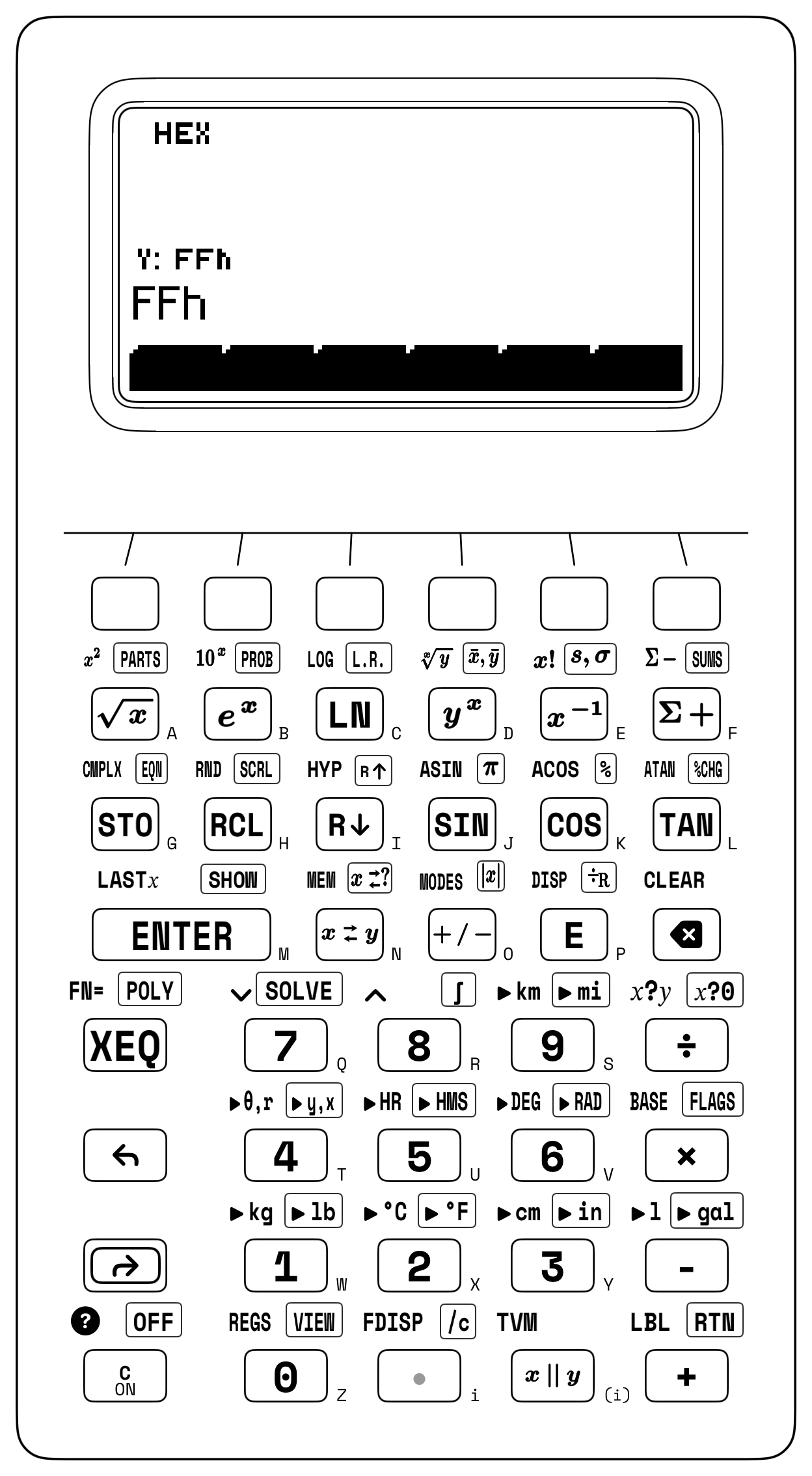
- Positional Radix Mode (
[↰] [BASE]): Left-shifted[↰] [BASE]on[×]presents the softkeys \(\mathtt{[HEX]} \;\; \mathtt{[DEC]} \;\; \mathtt{[OCT]} \;\; \mathtt{[BIN]}\), where Decimal (DEC) is the default radix and tappingHEX([HEX], suffixh, Figure 10.1),OCT([OCT], suffixo), orBIN([BIN], suffixb) re-renders all four stack registers (T, Z, Y, X) in place within the HP-32SII signed 36-bit word bounds (\([-2^{35},\; +2^{35}-1] = [-34,359,738,368,\; +34,359,738,367]\), flaggingTOO BIGwhen switching radix on larger decimal values) without altering their underlying values. Negative integers format in 64-bit two's-complement representation (FFFFFFFFFFFFFFFFhfor \(-1\), or masked to a \(k\)-bit unsigned field via Euclidean remainder[↱] [÷R]modulo \(2^k\), as with10000h [↱] [÷R]for 16 bits), and whenever Hexadecimal mode (HEX) is active, the six primary scientific keys across Row 1 ([√x],[eˣ],[LN],[yˣ],[1/x],[Σ+]) map to the printed hexadecimal digitsAthroughF. - Euclidean Quotient-and-Remainder Division (
[↱] [÷R]): Bitwise shifts, masks, and modular reduction execute directly on the stack: placing any non-negative integer \(N\) in Register \(Y\) and a positive divisor \(M\) (such as a bit boundary \(M = 2^k\) or modulus \(M = 1,000\)) in Register \(X\) and pressing[↱] [÷R](right-shifted on[E]) deposits the integer quotient \(\lfloor Y / X \rfloor\) into Register \(X\) and the remainder \(Y \bmod X\) into Register \(Y\) (so pressing[↱] [÷R]followed by[x⇄y]brings the modulo remainder \(Y \bmod X\) into Register \(X\)):
| Bit-Field / Masking Operation | Mathematical Equivalent (\(M = 2^k\)) | Stack Input (Y, X) |
Result Location |
|---|---|---|---|
| Left Shift (\(X \ll k\)) | \(X \times 2^k\) | \(Y = X,\; X = 2^k\) | Shifted word \(X \cdot 2^k\) in X |
| Right Shift (\(X \gg k\)) | \(\lfloor X / 2^k \rfloor\) | \(Y = X,\; X = 2^k\) | Upper bits \(\lfloor X / 2^k \rfloor\) in X |
| Low-Bit Mask (\(X \ \& \ (2^k - 1)\)) | \(X \bmod 2^k\) | \(Y = X,\; X = 2^k\) | Low \(k\) bits \(X \bmod 2^k\) in Y |
| High-Bit Alignment (\(X \ \& \ \sim(2^k - 1)\)) | \(\lfloor X / 2^k \rfloor \times 2^k\) | Quotient \(\times 2^k\) | Aligned base address in X |
Set Disjoint Bit \(k\) (OR) |
\(X + 2^k\) | \(Y = X,\; X = 2^k\) | Updated word in X |
Clear Set Bit \(k\) (AND NOT) |
\(X - 2^k\) | \(Y = X,\; X = 2^k\) | Updated word in X |
32-Bit Unsigned Complement (NOT) |
\(\text{FFFFFFFF}_{16} - X\) | \(Y = \mathtt{FFFFFFFFh},\; X\) | Inverted 32-bit mask in X |
- Number-Theoretic Parts (
[↱] [PARTS]): Right-shifted[↱] [PARTS]on[√x]assigns \(\mathtt{[IP]} \;\; \mathtt{[FP]} \;\; \mathtt{[ABS]} \;\; \mathtt{[SGN]} \;\; \mathtt{[GCD]} \;\; \mathtt{[LCM]}\) to the softkey strip, whereGCDandLCMreplace two integers across \((Y, X)\) with their greatest common divisor or least common multiple. - Discrete Combinatorics & Seeded Random Generation (
[↱] [PROB]): Right-shifted[↱] [PROB]on[eˣ]opens \(\mathtt{[Cn,r]} \;\; \mathtt{[Pn,r]} \;\; \mathtt{[n!]} \;\; \mathtt{[RAND]} \;\; \mathtt{[SD]}\), evaluating unordered combinations \(\binom{n}{r}\) and ordered permutations \(P(n, r)\) from \((Y = n,\; X = r)\), whileRANDpushes a uniform pseudo-random variate \(U \in [0, 1)\) onto Register \(X\) (with stack lift) andSDseeds the generator from the integer in Register \(X\) (and drops the stack) to replay reproducible Monte Carlo sequences.
10.3.1 Euclidean Word Cleavage & Number-Theoretic Ladders on the Stack
On the two clock domains \(a = 1,071\text{ MHz}\) and \(b = 462\text{ MHz}\), three Euclidean quotient-and-remainder steps (÷R) walk down Euclid's Remainder Ladder across Registers \(Y\) and \(X\): cleaving \(1,071\) by \(462\) leaves remainder \(R_1 = 147\) in \(Y\) and quotient \(Q_1 = 2\) in \(X\); cleaving \(462\) by \(147\) leaves \(R_2 = 21\) in \(Y\) and \(Q_2 = 3\) in \(X\); and cleaving \(147\) by \(21\) leaves remainder \(0\) in \(Y\), matching the PARTS softkeys GCD (\(\mathbf{21\text{ MHz}}\)) and LCM (\(\mathbf{23,562}\)).
Greatest-common-divisor reduction and integer-part extraction also govern aspect-ratio normalization, public-key coprimality checks, and fractional baud-rate synthesis. To reduce a \(1920 \times 1080\) display frame to its lowest aspect ratio, dividing both dimensions by \(\operatorname{GCD}(1920, 1080) = \mathbf{120}\) yields \(\mathbf{16:9}\); in RSA public-key cryptography, checking \(\operatorname{GCD}(e, \varphi(n)) = \mathbf{1}\) verifies that a candidate public exponent \(e = 65,537\) is coprime to Euler's totient \(\varphi(n)\), and in modular exponentiation by squaring, following each square with Euclidean division and a register swap reduces the intermediate product modulo \(m\) in place.
In an embedded UART clocked at \(f_{\text{clk}} = 150\text{ MHz}\) for \(115,200\text{ baud}\) (\(8\times\) oversampling divisor \(D = 150\times 10^6 / (8 \times 115,200) \approx 162.76\)), isolating the integer part extracts the 16-bit integer divider \(\mathbf{162}\) (A2h), while isolating the fractional part (\(\approx 0.76\)) and multiplying by \(64\) yields \(\approx 48.667 \to \mathbf{49}\) (31h) for the 6-bit fractional divider.
10.3.2 Combinatorial State Spaces & Birthday-Bound Collision Sizing
When drawing \(r\) items without replacement from \(n\) distinct items (such as \(n = 16\) hexadecimal digits 0–F or \(n = 12\) server racks), the counting law depends on whether the order of selection is significant. When order matters (for example, assigning \(r = 4\) distinct hexadecimal nibbles to a 4-stage shift register), there are \(n\) choices for the first slot, \(n - 1\) for the second, down to \(n - r + 1\) for the \(r\)-th slot, which defines the ordered permutation:
When order does not matter (for example, wiring every pair of \(r = 2\) routers among \(n = 7\) core nodes, yielding \(\binom{7}{2} = 21\) links), dividing \(P(n, r)\) by the \(r!\) internal rearrangements of the chosen subset yields the binomial coefficient (obeying symmetry \(\binom{n}{r} = \binom{n}{n-r}\) and Pascal's recurrence \(\binom{n}{r} = \binom{n-1}{r-1} + \binom{n-1}{r}\)):
When drawing \(L\) independent symbols with replacement from an alphabet of \(A\) equiprobable characters (such as a random passphrase of length \(L\) over \(A = 62\) alphanumeric characters or \(A = 2,048\) BIP-39 mnemonic words), there are \(N = A^L\) possible keys, corresponding to a Shannon cryptographic keyspace entropy of:
Every additional bit of entropy doubles the brute-force search work required by an adversary (\(2^H\) trial decryptions worst-case, \(2^{H-1}\) on average). Thus a 56-bit DES key (\(2^{56} \approx 7.21 \times 10^{16}\) keys) falls within hours to parallel hardware, while a 128-bit AES key (\(2^{128} \approx 3.4 \times 10^{38}\) keys), a 12-word BIP-39 mnemonic seed (\(12 \times \log_2(2,048) = \mathbf{132\text{ bits}}\)), or a 16-character random alphanumeric password (\(H = 16 \log_2 62 \approx \mathbf{95.267\text{ bits}}\), spanning \(62^{16} \approx \mathbf{4.767 \times 10^{28}\text{ keys}}\)) remains computationally infeasible against exhaustive search.
In Decimal mode, staging \(n\) in Register \(Y\) and \(r\) in Register \(X\) evaluates discrete combinatorial state spaces from the probability menu: for a 12-drive storage array, selecting \(5\) drives for an unordered RAID parity group yields \(\binom{12}{5} = \mathbf{792}\) distinct drive subsets; ordering \(5\) drives into a sequential failover chain multiplies by \(5! = 120\) to yield \(P(12, 5) = \mathbf{95,040}\) ordered routes. When Monte Carlo hardware verification requires a repeatable stream of uniform pseudo-random test vectors \(U_k \in [0, 1)\), seeding the generator from a known integer \(S_0\) via SD guarantees that RAND replays the same sequence across every test bench.
The ratio between sampling without replacement \(P(N, k)\) and sampling with replacement \(N^k\) governs the Birthday Paradox. When \(k\) independent items (such as people in a room, TCP sequence numbers, or database records) are each assigned one of \(N\) equally likely labels (such as \(N = 365\) calendar days or \(N = 2^b\) possible values of a \(b\)-bit hash function), linear intuition suggests that a duplicate label becomes \(50\%\) likely only when \(k\) approaches \(N/2\). That linear estimate is far too large because a collision can occur across any of the \(\binom{k}{2} = \frac{k(k-1)}{2}\) distinct pairs among the \(k\) items—and \(\binom{k}{2}\) grows quadratically with \(k\). Dividing the ordered permutation \(P(N, k)\) by the \(N^k\) unrestricted assignments and applying the first-order Taylor bound \(1 - x \approx e^{-x}\) yields the Gaussian collision law and the square-root Birthday Bound:
For \(N = 365\) calendar days and \(k = 23\) people (\(\binom{23}{2} = 253\text{ pairs}\)), dividing \(P(365, 23) \approx 4.22 \times 10^{58}\) by \(365^{23}\) and subtracting from \(1\) confirms that a shared birthday occurs with probability \(\approx 1 - 0.493 = 0.507\) (\(\approx \mathbf{50.73\%}\)). Across \(b\)-bit digital identifiers (\(N = 2^b\)), where the \(50\%\) collision threshold scales as \(1.177 \times 2^{b/2}\), a 32-bit CRC-32 or IPv4 packet ID (\(N = 2^{32} \approx 4.295 \times 10^9\)) reaches a \(50\%\) collision risk after just \(k_{50\%} \approx \sqrt{2\ln 2} \times 2^{16} \approx \mathbf{77,163}\) frames, and a 64-bit block cipher initialization vector (\(N = 2^{64}\)) reaches \(50\%\) collision after \(k_{50\%} \approx 1.177 \times 2^{32} \approx \mathbf{5.06 \times 10^9}\) blocks (~\(32\text{ GB}\) of data). At 128 bits, a random UUIDv4 (\(b = 122\) random bits) requires \(k_{50\%} \approx \mathbf{2.71 \times 10^{18}}\) UUIDs, and a 256-bit SHA-256 digest (\(N = 2^{256} \approx 1.158 \times 10^{77}\)) requires \(k_{50\%} \approx \mathbf{4.01 \times 10^{38}}\) hashes before a random collision becomes \(50\%\) likely.
10.3.3 Unpacking Multi-Byte Network Words: IPv4 CIDR Subnets & Flash Pages
In systems and network engineering, cleaving binary words at powers of two (\(2^k\)) unpacks multi-byte network addresses, flash memory pages, and Base64 character streams across the four visible registers. Every IPv4 address \(A\) on the Internet is an unsigned 32-bit integer written in dotted-quad decimal notation \(B_3.B_2.B_1.B_0\) as four 8-bit octets (0 to 255, or 00h to FFh), packed via Horner's radix-256 polynomial \(A = ((B_3 \cdot 256 + B_2)\cdot 256 + B_1)\cdot 256 + B_0\). Chaining three Euclidean divisions by \(256\) on the 32-bit unsigned integer \(3,232,235,777\) peels off the four base-256 octets one by one until all four dotted-quad numbers (192.168.1.1) sit together across Registers \(T, Z, Y,\) and \(X\):
| Keystroke | Register T | Register Z | Register Y | Register X | What Happens on the Stack |
|---|---|---|---|---|---|
3232235777 [ENTER] 256 [↱] [÷R] |
0 |
0 |
1 |
12625921 |
Peel Octet 4 (\(B_0 = 1\)) into \(Y\); upper 24-bit prefix in \(X\) |
256 [↱] [÷R] |
0 |
1 |
1 |
49320 |
Peel Octet 3 (\(B_1 = 1\)) into \(Y\); upper 16-bit prefix in \(X\) |
256 [↱] [÷R] |
1 |
1 |
168 |
192 |
Peel Octet 2 (\(B_2 = 168\)) in \(Y\), Octet 1 (\(B_3 = 192\)) in \(X \implies \mathtt{192.168.1.1}\) |
Once that power-of-two cleavage pattern is understood, any memory or network boundary splits the same way. For the byte address \(12,345 = 771 \times 16 + 9\) (0x3039), cleaving by \(2^4 = 16\) separates the 16-byte cache-line row index \(Q = \mathbf{771}\) in Register \(X\) from the intra-line byte offset \(R = \mathbf{9}\) in Register \(Y\); cleaving that same byte address \(12,345\) by \(2^8 = 256\) for a SPI NOR flash chip splits the word at Bit 8 into Flash Page \(Q = \mathbf{48}\) (30h) in Register \(X\) and intra-page byte offset \(R = \mathbf{57}\) (39h) in Register \(Y\).
In Classless Inter-Domain Routing (CIDR), on a /28 office VLAN subnet (255.255.255.240, where \(32 - 28 = 4\) host bits define a block stride of \(2^4 = 16\) addresses), cleaving host octet 205 by 16 places block index \(12\) in Register \(X\) and host offset \(13\) in Register \(Y\), and multiplying \(12 \times 16\) zeroes out the low 4 host bits to align to the /28 network base ID 192 (while on a /24 workstation address 192.168.10.45 \(= \mathtt{C0A80A2Dh}\), cleaving by \(2^8 = \mathtt{100h}\) and multiplying back by 100h aligns the network base to C0A80A00h and adding the host wildcard FFh yields the broadcast address C0A80AFFh).
Base64 encoding (RFC 4648) is the 24-bit four-register cousin of IPv4 unpacking. Welding three 8-bit ASCII bytes "Man" (4D616Eh) into a single 24-bit integer and cleaving it three times by \(2^6 = 64\) (\(\mathtt{40h}\)) peels off the four 6-bit Base64 character indices across all four stack registers (\(X = \mathtt{13h} = 19 \to \mathtt{'T'}\), \(Y = \mathtt{16h} = 22 \to \mathtt{'W'}\), \(Z = \mathtt{5h} = 5 \to \mathtt{'F'}\), and \(T = \mathtt{2Eh} = 46 \to \mathtt{'u'}\)) to spell TWFu.
10.3.4 Bit-Field Shift-and-Merge Packing: RGB565 Pixels & GPIO Masks
A microcontroller display framebuffer packs three Red, Green, and Blue brightness channels into a single 16-bit unsigned pixel word (RGB565), allocating 5 bits (\(R_5 \in [0, 31]\), 00h–1Fh) to Red in Bits 15–11, 6 bits (\(G_6 \in [0, 63]\), 00h–3Fh) to Green in Bits 10–5 (matching the human retina's peak photopic sensitivity to green), and 5 bits (\(B_5 \in [0, 31]\), 00h–1Fh) to Blue in Bits 4–0:
In 16-bit RGB565 display graphics, 5-bit Blue (6h \(= 6\)), 6-bit Green (15h \(= 21\)), and 5-bit Red (1Fh \(= 31\)) staged across the stack in Hexadecimal mode shift Red left by 11 bits (× 800h \(\to \mathtt{F800h}\)), swap Green into Register \(X\) to shift left by 5 bits (× 20h \(\to \mathtt{2A0h}\)), and merge all three disjoint bit lanes into the 16-bit pixel word FAA6h (\(64,166_{10}\)). In the reverse direction, cleaving FAA6h at Bit 11 (\(2^{11} = \mathtt{800h}\)) places the 11-bit remainder 6A6h in Register \(Y\) and the 5-bit Red quotient 1Fh (\(31_{10}\)) in Register \(X\), so swapping Registers \(X\) and \(Y\) moves 6A6h into Register \(X\) (and 1Fh into Register \(Y\), lifting to Register \(Z\) when 20h is entered) before cleaving by \(2^5 = \mathtt{20h}\) to leave Red 1Fh (\(31_{10}\)) in Register \(Z\), Blue 6h (\(6_{10}\)) in Register \(Y\), and Green 15h (\(21_{10}\)) in Register \(X\). Because all four stack registers persist across radix changes, mixed-radix mask synthesis (for example, staging a hexadecimal register offset 3A7h (\(935_{10}\)), switching to octal (1647o) to add a UNIX permission mask 452o (\(298_{10}\)), and viewing the combined mask 2321o as decimal \(\mathbf{1,233_{10}}\) or hexadecimal \(\mathbf{\mathtt{4D1h}}\)) requires no re-entry when switching bases.
10.3.5 IEEE-754 Floating-Point Bit Unpacking, Checksums & Endianness
Multi-byte memory architectures follow either Big-Endian or Little-Endian byte ordering. Network protocols transmit bytes Big-Endian (12345678h, most-significant byte 12h first), while x86, ARM, and RISC-V processors store bytes Little-Endian (78563412h, least-significant byte 78h at the lowest memory address). Reversing the 32-bit Big-Endian word 0x12345678 into its Little-Endian mirror 0x78563412 (BSWAP) promotes Byte 0 (78h \(\times \mathtt{1000000h} = \mathtt{78000000h}\)), Byte 1 (56h \(\times \mathtt{10000h} = \mathtt{560000h}\)), and Byte 2 (34h \(\times \mathtt{100h} = \mathtt{3400h}\)), and demotes Byte 3 (\(\lfloor \mathtt{12345678h} / \mathtt{1000000h}\rfloor = \mathtt{12h}\)), summing to 78563412h.
When routers verify IPv4, TCP, and UDP packet integrity in flight, they use RFC 1071 16-bit one's-complement addition with end-around carry (Knuth, 1997). Because folding upper carries from Bit 16 back into Bit 0 makes 16-bit addition cyclically symmetric, Big-Endian and Little-Endian machines compute the same checksum without byte-swapping. For an IPv4 header whose ten 16-bit words sum to 2653Dh, cleaving at \(2^{16} = \mathtt{10000h}\) separates the upper carry quotient 2h from the lower 16-bit sum 653Dh, folding to 653Fh (653Dh + 2h) and inverting against FFFFh (FFFFh - 653Fh) to yield the wire checksum 9AC0h. That same two-register end-around carry implements a circular 1-bit left rotation (ROL 1) across an 8-bit register boundary (\(2^8 = \mathtt{100h}\)): doubling 85h (\(1000\,0101_2\)) shifts the byte left to 10Ah, cleaving by 100h separates the low byte 0Ah from the Bit 8 carry 1h, and adding them folds the carry into Bit 0 to give \(\operatorname{ROL}_8(\mathtt{85h}, 1) = \mathbf{\mathtt{0Bh}}\) (\(0000\,1011_2\)).
Finally, the IEEE-754 floating-point standard (IEEE, 2019; Golub & Van Loan, 1996; Parker, 2019) writes any normal non-zero real number \(x\) in normalized base-2 scientific notation by slicing a fixed-width binary word into three contiguous bit-fields: a 1-bit sign flag \(S \in \{0, 1\}\), an unsigned biased exponent integer \(E\) offset by a fixed midrange constant \(\text{bias}\), and a \(p\)-bit unsigned fraction integer \(M \in [0, 2^p - 1]\) representing the trailing binary digits after an implicit leading 1. bit (whose least-significant step \(2^{-p}\) defines the machine epsilon spacing \(\varepsilon_{\text{mach}}\) between \(1\) and the next representable floating-point number):
Those three multiplicative fields separate sign, scale, and precision in hardware: \((-1)^S\) sets the algebraic sign (\(+1\) when \(S = 0\), \(-1\) when \(S = 1\)), the power-of-two factor \(2^{E - \text{bias}}\) selects the binary octave window (allowing unsigned integer comparators to sort exponents directly without a separate exponent sign bit), and the significand factor \(1 + M/2^p = (1.M)_2\) subdivides that octave into \(2^p\) uniform steps of relative width \(\varepsilon_{\text{mach}} = 2^{-p}\) while omitting the invariant leading 1. bit from storage to gain one extra bit of precision. For 32-bit single precision (binary32, \(p = 23\) explicit mantissa bits, \(\text{bias} = 127\)), \(\varepsilon_{\text{mach}} = 2^{-23} \approx \mathbf{1.192 \times 10^{-7}}\) (\(\sim 7.2\) decimal digits); for 64-bit double precision (binary64, \(p = 52\) explicit mantissa bits, \(\text{bias} = 1023\)), \(\varepsilon_{\text{mach}} = 2^{-52} \approx \mathbf{2.22 \times 10^{-16}}\) (\(\sim 15.95\) decimal digits).
A raw IEEE-754 floating-point word unpacks via the same two-step Euclidean cleavage as an RGB565 pixel. Because the SC-32's signed 36-bit integer word places its sign boundary at Bit 35, any 32-bit unsigned bit pattern like 0xC0C80000 (\(3,234,332,672_{10}\), representing binary32 \(-6.25_{10}\)) sits inside Bits 31–0 as a non-negative integer. Cleaving C0C80000h first at Bit 23 (\(2^{23} = \mathtt{800000h}\)) and then cleaving the upper 9-bit quotient (181h) at Bit 8 (\(2^8 = \mathtt{100h}\)) deposits the 23-bit mantissa 480000h (\(4,718,592 / 2^{23} \approx 0.563\), or \(\approx 1.563\) with the hidden 1.) into Register \(Z\), the 8-bit biased exponent 81h (\(129_{10}\), so \(e = 129 - 127 = 2\)) into Register \(Y\), and the sign bit 1h into Register \(X\), verifying \((-1)^1 \times 2^2 \times (1 + 4,718,592 / 2^{23}) = \mathbf{-6.25}\).
For the upper 32-bit word 0xC02AC000 of 64-bit binary64 \(-13.375_{10}\), cleaving at \(2^{20} = \mathtt{100000h}\) and \(2^{11} = \mathtt{800h}\) isolates \(S = 1\), \(E = \mathtt{402h} = 1026\) (\(e = 1026 - 1023 = 3\)), and mantissa fraction \(\mathtt{AC000h} / 2^{20} \approx 0.672\) to reconstruct \((-1)^1 \times 2^3 \times (1 + \mathtt{AC000h}/2^{20}) = \mathbf{-13.375}\).
10.3.6 Try It on the Stack
- Euclidean Quotient-and-Remainder Reconstruction & Modular Exponentiation: In Decimal mode, cleave \(N = 250\) by \(M = 16\) using quotient-and-remainder division to place remainder \(R = 10\) in Register \(Y\) and quotient \(Q = 15\) in Register \(X\), then restore \(M = 16\) via
LASTX, multiply by \(Q\), and add \(R\) to reconstruct \(N = \mathbf{250}\); next, find the last three digits of \(7^8 \bmod 1,000\) by squaring \(7 \to 49 \to 2,401\), cleaving by \(1,000\) and swapping Registers \(X\) and \(Y\) to isolate the remainder \(401\), squaring \(401 \to 160,801\), and cleaving by \(1,000\) and swapping once more. (Verified Register \(X\) results: \(\mathbf{250}\) and \(7^8 \bmod 1,000 = \mathbf{801}\).) - Unpacking a 16-Bit
RGB565Pixel Word: In Hexadecimal mode, cleave the 16-bit color wordF38Ehfirst at Bit 11 (800h), swap Registers \(X\) and \(Y\) to bring the lower 11-bit remainder (38Eh) into Register \(X\), and then cleave at Bit 5 (20h) to separate all three color channels across Registers \((Z, Y, X)\). (Verified stack result: Red \(Z = \mathbf{\mathtt{1Eh}}\) (\(30_{10}\)), Blue \(Y = \mathbf{\mathtt{Eh}}\) (\(14_{10}\)), and Green \(X = \mathbf{\mathtt{1Ch}}\) (\(28_{10}\)).) - End-Around Carry RFC 1071 Checksum Fold: In Hexadecimal mode, fold the 17-bit header accumulator sum
10000hacross the 16-bit boundary10000hvia quotient-and-remainder division and addition (\(0 + 1 = \mathtt{1h}\)), then subtract from the 16-bit all-ones maskFFFFh(by keyingFFFFh, swapping Registers \(X\) and \(Y\), and subtracting) to form \(\mathtt{FFFFh} - \mathtt{1h}\), the one's-complement wire checksum. (Verified Register \(X\) result: \(\mathbf{\mathtt{FFFEh}}\) (\(65,534_{10}\)).)