A Tool-Free Calculator Built Around a Sliding Assembly
“Tool-free” is easy to write on a feature list and hard to make useful in a printed enclosure. The test is not whether an assembly has no screws; it is whether a person can insert, retain, inspect, and later release the parts without turning every opening into a breakage risk.
The current StackCalc assembly is an unpowered, four-part mechanical prototype: a tapered chassis, unified faceplate, TPU membrane, and snap-retained top cap. Its RP2350 KiCad board is in fabrication, but no assembled board has been installed, so this remains a mechanical design lesson rather than an electronics assembly claim.
Choose one insertion story
Before adding catches or details, write the assembly sequence in verbs. Ours is: align the faceplate and membrane with the chassis rails, slide them squarely into the capture path, then seat the top cap into its snap-retention features. A part should not need to flex in two incompatible directions while it is being inserted.
That sentence is a design tool. It forces every feature to have a job: rails guide and retain, lead-ins tolerate approach error, shoulders define the seated position, and the cap catches hold the final closure. If a feature does none of those, it is likely decoration or an obstacle.
Design the four mechanical functions separately
- Guide: use a clear entry direction and a generous lead-in so the user can find the rail without seeing the hidden interface.
- Capture: make the rail overlap or channel keep a seated part from moving in the wrong direction.
- Stop: give the part a defined seated position instead of relying on friction alone.
- Release: provide a deliberate way to reopen the assembly without prying against a thin display surround or the flexible membrane.
Keeping these functions separate makes an FDM prototype easier to tune. A tighter rail is not automatically better if it also removes the only practical lead-in. A stronger snap is not better if the release point becomes inaccessible.
Use printed experiments to reject a direction
Before selecting the current TPU membrane direction, we printed integrated spring and key fixtures. The experiments converted vague questions—can the part print, return, and tolerate the geometry?—into artifacts we could inspect. They did not establish final key force, fatigue life, or the behavior of the current membrane.
A useful prototype record names both the decision an experiment informed and the question it did not answer. The previous spring fixtures informed the investigation; they are not the current mechanism or evidence that the current assembly is qualified.
How to test a tool-free enclosure honestly
Start with simple observations on a named revision: insertion path, binding points, seating consistency, release access, and visible stress at snap features. Then add repeatable measurements: insertion and removal force, cap retention after repeated cycles, fit across multiple prints, and any damage after service. Pair each result with material, print profile, and sample count.
The matching STL exports and PrusaSlicer .3mf profiles make the current geometry reproducible. They are a starting point, not a promise of universal printer fit. The current project files and staged build log are available on the StackCalc Hackaday project.
Print the interfaces, then practise the sequence
The current build is intentionally small: chassis, faceplate, TPU membrane, and top cap. That makes it possible to inspect each interface instead of burying several unknowns inside a finished-looking case. The chassis rails establish direction; the lead-ins tolerate approach error; the shoulders identify the seated position; and the cap handles final retention.
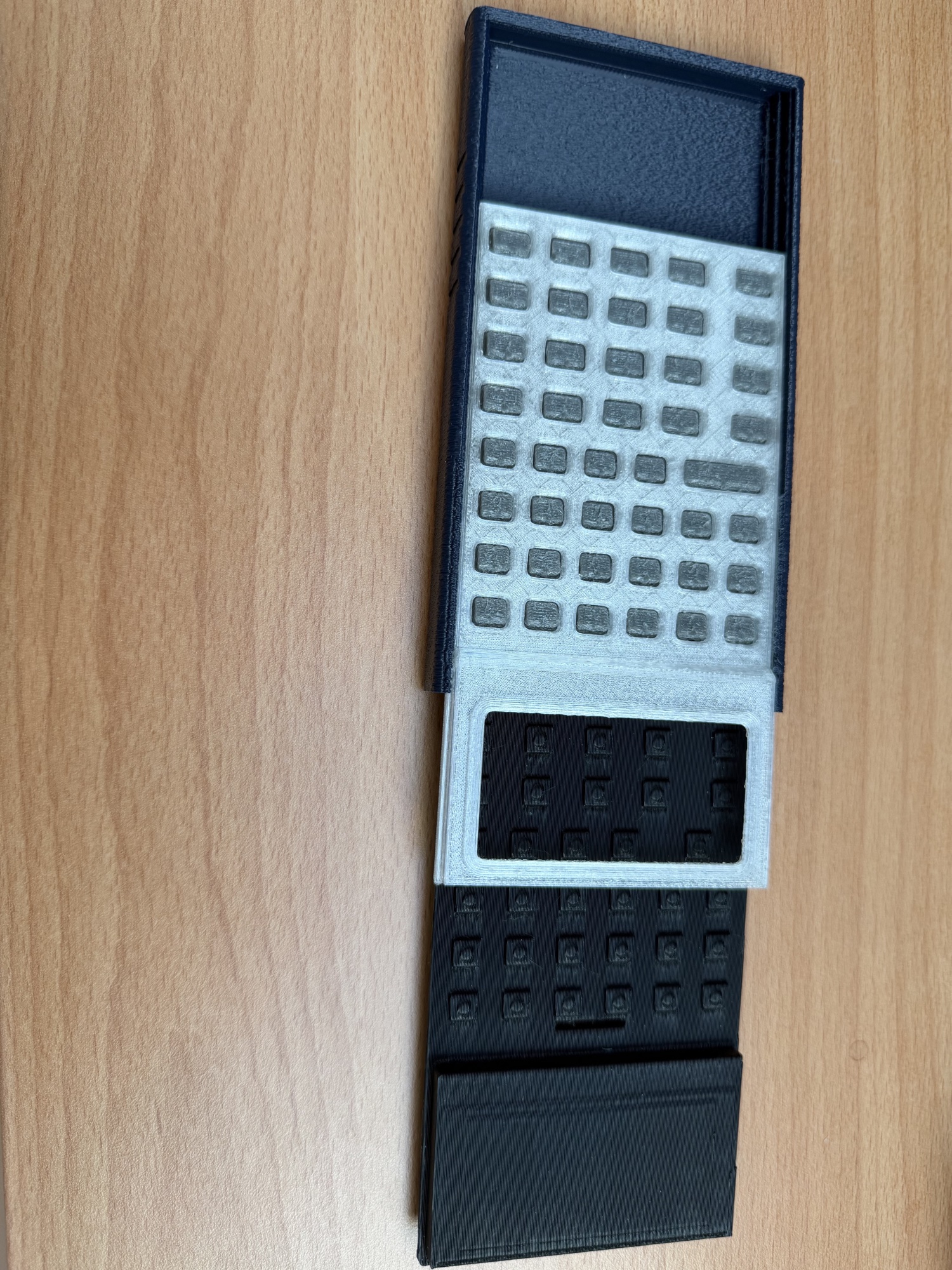
The matching STL files and PrusaSlicer 3MF profiles are staged with the project build materials. The 3MF projects matter because print orientation, support placement, layer height, and per-part overrides influence whether a slide fit behaves like the model. Start by printing the matching set, remove support carefully from mating surfaces, dry-fit the faceplate and membrane square to the rails, then close the cap through its intended catch features.
The calculator electronics are not installed in this prototype, but the KiCad board was designed around its envelope and is in fabrication. The next pass will use the board to check the same interfaces under real display, connector, and switch constraints. Until then, the stand and packaging article shows how the same printed design work extends beyond the enclosure.